5.6 KiB
Concept2 Related Information
Settings
Profile for Concept2
Model C
The Model C has 3 magnets on the flywheel giving: numOfImpulsesPerRevolution: 3, minimumTimeBetweenImpulses: 0.010, maximumTimeBetweenImpulses: 0.044,
'autoAdjustDragFactor: true' here as well, which is doable for the Concept2: Setting it to true, will allow Open Rowing Monitor to automatically calculate the drag factor based on the flywheelInertia and the on the measured values in the stroke recovery phase. See: ./rower_settings.md
Concept2 Model C Config from beta repo.
  // Concept2 RowErg, Model B and C
  Concept2_Model_C: {
    numOfImpulsesPerRevolution: 3,
    sprocketRadius: 1.4,
    minimumTimeBetweenImpulses: 0.014,
    maximumTimeBetweenImpulses: 0.040,
    smoothing: 1,
    flankLength: 6,
    minumumForceBeforeStroke: 50,
    minumumRecoverySlope: 0.00070,
    minimumStrokeQuality: 0.36,
    autoAdjustRecoverySlope: true,
    autoAdjustRecoverySlopeMargin: 0.01,
    minimumDriveTime: 0.400, // minimum time of the drive phase
    minimumRecoveryTime: 0.900, // minimum time of the recovery phase
    dragFactor: 110,
    autoAdjustDragFactor: true,
    dragFactorSmoothing: 3,
    minimumDragQuality: 0.95,
    flywheelInertia: 0.10148,
    maximumStrokeTimeBeforePause: 6.0,
    magicConstant: 2.8
  }
Hardware
Model C Hardware
For the Rpi to register the logical high for the pin (it has a practical logical high voltage of above 1.6-1.8v but according to the specs 2.5v is where 100% that high is registered).
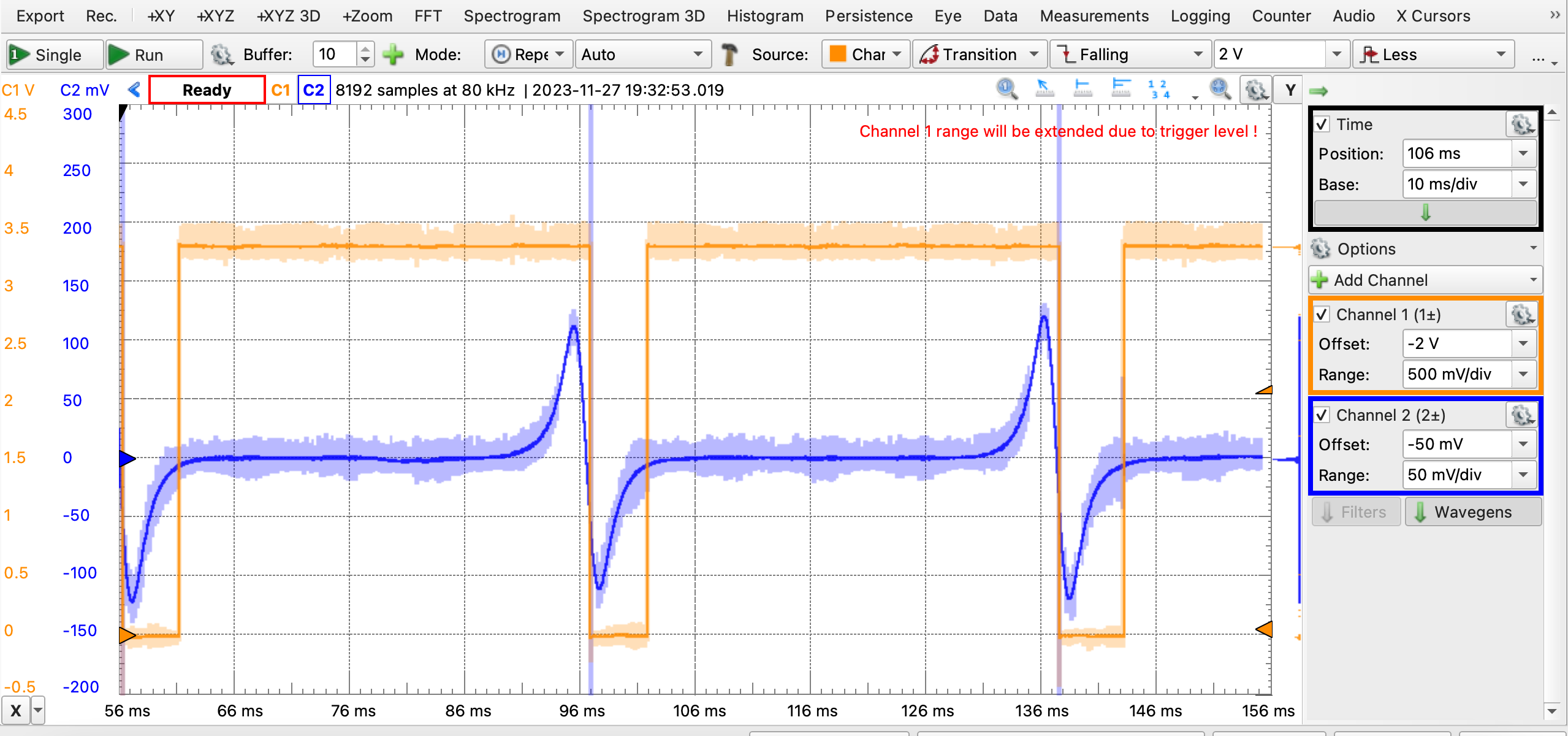
A Concept2 Model C output peaks at ~20mV when rowing at moderate intensity, even if it peaked at 50mV when rowed by an Olympian that is still far too low for the desired 2.5V to consistently read high on a RPi GPIO.
The module C uses a reluctance sensor
A wire coil with a ferrite core 105ohms) if you replace the magnets ensure that the ‘south’ is facing the sensor.
Here's the C pulse train:
2023-11-28_05-35-19_rowingData.csv
MAX9924 Variable Reluctance Sensor Interface
£4 per piece on aliexpress
These are signal conditioning IC's that connect to the Reluctance sensor and provide a pwm signal to the microcontroller
The MAX9924 uses a zero crossing with dynamic threshold to avoid the zero- crossings in the noise, but still work with a range of signal strength.
- MAX9924 ORM PiHat
- Extra discussion See: /space/code_repositories/hardware/kicad/open_rowing_monitor
- The Extra linked page also has a config.js for a Model C using the max9924. The layout does not use a ground plane.
- MAX9924UEVKIT See: /space/code_repositories/hardware/kicad/MAX9924UEVKIT
MAX9926 Variable Reluctance Sensor Interface
$0.81 per piece on aliexpress
This are the two sensor capable IC's which allows them to be used for quadrature direction sensing of one sensor or reading from two sensors.
- MAX9926UEVKIT See: /space/code_repositories/hardware/kicad/MAX9926UEVKIT/
- rusefi max9926
Model D
The Model D has 6 magnets on the flywheel with a coil/generator setup giving: numOfImpulsesPerRevolution: 6, minimumTimeBetweenImpulses: 0.005, maximumTimeBetweenImpulses: 0.022,
The Model D has some uptake issues in its generator: the first x pulses are very weak, but when the flywheel gains momentum, it will peak at 15V.
Arduino Monitor for Concept2 Model B C D
This project uses an arduino mega 2560 with has 5V tolerant pins but uses analog read.
Model B and C
Just add 100k resistor inline with the cable that comes from flyweel (2.5mm TRS
jack) to the analog read pin (1) on the arduino.

Drag factor
For a new Concept2, the Drag Factor ranges between 80 (Damper setting 1) and 220 (Damper setting 10):
- concept 2 model c damper level 01 oscilloscope data.txt
- concept 2 model c damper level 10 oscilloscope data.txt
Model A,C,D,and E has 14 tooth gear
Model B drag factor is different requiring a little recalculating.
The resistance is determined by cubing the number of teeth on the sprockets.
13 x 13 x 13 = 2197 (Model B, small wheel) 14 x 14 x 14 = 2744 (Models C/D/E) 15 x 15 x 15 = 3375 (Model B, big wheel)